|
|
| Nuclear Products - Data Acquisition Systems |
|
|
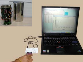 |
Pipe Monitor or Pipe Inspection Gauge (PIG) is a battery operated instrument complete
with 1" x 1" thick or 2" x 2" NaI(Tl) detector, Voltage Divider and Preamplifier
for the detector. HV Supply for PMT, Pulse Processing & Counter/Timer circuitry
and Flash Card for data storage are internal part of the Pipe Inspection Gauge.
Entire equipment is housed in a water-tight Stainless Steel container. The SS container
is strong enough to withstand the tumbling and shocks inside the pipeline while
traveling from one end to the other. Pipe Monitor works on 8 C type Dura cells.
Typical battery life is more than 30 hours. This enables user to use the PIG without
changing the batteries even after one or two experiments. |
|
PIG is a micro controller based single channel data acquisition system. It has front
end electronics compatible to NaI(Tl) detector. The incident radiation produces
the sharp pulses as output of PMT. These pulses are shaped to TTL output for counting.
Micro controller based counter counts these pulses and stores them in the Flash
Card memory. The use of Flash Card reduces the down loading time of the data when
the PIG is retrieved after the pipe inspection.
Initialisation of Flash Card, setting of counting time are accomplished by the software
program. This program checks the integrity of the Flash Card for writing data. Once
the time parameter is set, PIG is ready to acquire the counts data for a period
over 20 hours.
Reading of Flash Card is done with use of another Windows based program 'PIG Reader'.
This program downloads the raw counts and events and converts them in a text or
Excel File for later use. The graphic display is provided to quickly check the peaks
in the Counts Vs Time histogram. |
Specifications : |
| Pipe Monitor |
| Detector |
: |
2" dia x 2" thick, NaI(Tl) Detector with PMT integral assembly or detector of specific
size. |
| Resolution |
: |
8% or better for Cs-137 |
| Electronics |
| Voltage Divider |
: |
Suitable for above NaI(Tl) detector |
| HV Supply |
: |
0 to 1000 Volts as required by PMT, internally set |
| Pulse Processing |
: |
Preamplifier suitable for the detector with adequate pulse shaping and discrimination
for different Counter |
| Counter |
| Input |
: |
TTL pulse internally connected to pulse shaper |
| Counting Time |
: |
Externally programmable from 1 to 999 sec with step of 1 sec |
| Maximum Counts |
: |
15777 K ( 3 Bytes)/Counting Time |
| Maximum Counts |
: |
Maximum up to 1,00,000 |
| Data Storage |
: |
Flash Card Memory |
| Mechanical |
| Enclosure |
: |
Water tight Stainless Steel cylindrical enclosure |
| Dimensions |
: |
150 mm (6") dia x 300 mm (12") long |
| Electrical |
| Battery Power |
: |
Standard Dry Cells or 8 nos Dura Cells, 8 nos |
| Battery Life |
: |
20 hours Minimum |
| Data Retrieval |
: |
Windows based for downloading the stored counts data to PC |
|
|
Top |
|
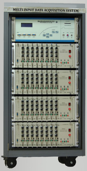 |
Multi Input Data Acquisition System acronymed as MIDAS has been designed to cater
the requirement of multi detector based tracer experiments. Typical application
of such systems is in oil & Chemical industries, FCCU experiments and in gamma ray
tomography experiments. A short lived radio isotope is injected in reactor column
before start of the experiment. As the process starts, the radio activity moves
along with the process fluid. NaI(Tl) detectors are mounted outside the column to
detect the radio activity. As the radio activity comes near the detector, more number
of gamma radiations fall on the detector, which results in more number of photon
generation. Using the photo multiplier tubes (PMTs) these photons are converted
to electrical energy.
Data acquisition system designed by Para Electronics, comprises of Preamplifier,
spectroscopy amplifier, single channel analyzer & high voltage supply for each detector.
The number of detectors will depend upon the user requirements. So far we have supplied
8, 10, 16 channel data acquisition systems. Flexibility in the design of this system
enables the user to decide on the no. of channels, which can be expanded to 32 channels.
The system can be modified as per the user requirements.
Typical NaI(Tl) detector is of size 1” dia x 1” thick mounted on 1” dia PMT, housed
in Aluminum enclosure. The voltage divider resistors are integral part of the detectors.
Each channel has one detector. High voltage supply is required for PMTs to convert
photon into electrical energy. This high voltage supply can be provided on the detector
side or in the control room. Data acquisition system is normally kept in a control
room & cables run from control room to the detector. Cable length can be upto 60mtrs.
For cable length more than 20 mtrs
The system is designed for Na (I)T1 and BG0 detectors. For 12 or 14 pin detectors
preamplifier is supplied at the detector end. For G1 type detectors, preamplifier
is not required at the detector end. For such detectors cable length is restricted
upto 20 mtrs only. For 12 or 14 pin detectors, cable length can be upto 60 mtrs. |
|
The system is designed in a modular form. For each channel, a separate spectroscopy
amplifier & single channel analyzer is available. A 12 slot NIM bin accommodates
a power supply (+5V, ±15V), eight modules of spectroscopy amplifier & single channel
analyzer for eight channel inputs and a common interface module to transfer eight
SCA outputs to a counter unit. Thus for 16 channel data acquisition system, two
such BINS will be provided. For 32 channel system, four BINS will be provided. Spectroscopy
amplifier has a base line restorer circuit to take care of higher count rates. Single
channel analyzer can operate in threshold or window mode depending upon the internal
jumper setting. All SCA outputs are routed through back panel connectors to a common
interface module from interface module, these outputs (TTL) are taken to a counter
unit (MIDAS).
Counter unit, takes care of all the channels i.e. for 32 channel system, counter
unit will have 32 input channels. For control of this counter unit, PC based software
will be provided. This counter unit can operate in online or offline mode. In online
mode, the unit will be controlled by PC based software package. User can set the
dwell time and number of events through this package. Once the acquisition starts,
data for the selected channel will be transferred to PC after completion of each
event. Data transfer will be through USB Communication. User can select any channel
as per his requirement. Only selected channel will be active during data acquisition.
In online mode, user will be able to see the data in graphical format. After completion
of set events, data will be available in a text file. User can use this file for
further processing. In offline mode 250 MB flash card will be provided for data
storage. This flash card will store the data for selected channels in a file format.
Offline mode is possible in applications where the dwell time is in seconds.
The pulse processing electronics front end circuits are fitted in modules. 8 such
modules are housed in a 19” wide BIN. A common enclosure can accommodate more than
1 such BINs.
Software plays a very important role in the design of MIDAS system. Assembly level
software handles the hardware. higher level Windows based software is provided for
data acquisition control, data transfer and graphic presentation on PC. Data storage
and retrieval are in built features of this software. |
|
|
Top |
|
|
|
| Copyright © 2011 Electronic Enterprises (India) Private Limited |
|
|
|